


DIY Contact Pad Antennas
🔌 Build a Capacitive Contact Pad for Covert Signal Detection
⚠️ Warning: Don’t Connect Raw Pads Directly to Your Analyzer
❌ Never connect a raw contact pad (like an EEG electrode or copper plate) directly to the BB60C or any spectrum analyzer.
✅ These sensors can carry DC bias, high impedance, and even static discharge that could destroy the analyzer input.
You must add a buffer amplifier, DC-blocking capacitor, or attenuated bias tee between the pad and the analyzer.
Detect Tissue-Coupled and Near-Field EM Signals with an SMA-Connected Sensor
While most antennas are built to pick up radiated RF in the air, some of the most covert surveillance signals don’t radiate at all — they exist as capacitive fields that only form on the surface of the body or a nearby object.
To detect these signals, you need a capacitive contact pad, not a traditional antenna. In this post, we’ll show you how to build or adapt one for RF measurement tools with an SMA input, like the Signal Hound BB60C, an SDR, or a low-noise amplifier.
🧠 What Is a Capacitive Contact Pad?
A capacitive contact pad is a metallic surface (usually copper or aluminum) that picks up electric field disturbances caused by:
- Near-field emissions (within λ/2π)
- Tissue-coupled RF signals
- Capacitive coupling from implants
- Subtle EM modulations not radiated through air
Unlike antennas, which detect propagating waves, these pads detect electric field displacement — like a probe that “feels” the charge on a surface.
🧰 DIY Build Guide – SMA-Compatible Capacitive Pad
🔩 Parts Needed:
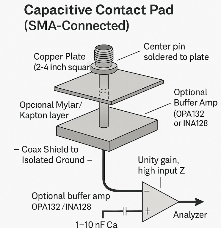
- ✅ Copper plate or aluminum sheet (2″–4″)
- ✅ SMA female bulkhead connector
- ✅ Coaxial cable (RG-174 or RG-316)
- ✅ Optional: OPA132 / INA128 / TL072 op-amp for buffering
- ✅ Optional: 1–10 nF capacitor for DC blocking
🛠️ Assembly Steps:
- Drill a hole in the copper plate for the SMA jack.
- Solder the center pin of the SMA directly to the copper or aluminum surface.
- Connect the coax shield to floating ground (NOT the subject).
- Mount to a non-conductive base (acrylic, plastic).
- Optionally: Add thin Kapton/Mylar insulation for non-contact use.
- Place a blocking capacitor and/or op-amp buffer inline before connecting to BB60C.
🧪 Buffer Amplifier (Highly Recommended)
If your analyzer or SDR has a 50 Ω input (like BB60C), it may attenuate or distort weak capacitive signals. Use a unity-gain buffer to protect both signal and hardware.
Buffer Design:
- Use OPA132, INA128, or similar
- High-Z input, 50 Ω output
- Series cap (1–10 nF) before SMA output
📈 Allows detection of sub-MHz signals like ELF/ULF modulation or implant telemetry.
🛡️ Commercial Protection/Interface Options
| Device | Description | Modifications |
|---|---|---|
| Thorlabs 50LD | High-Z voltage buffer (20 kΩ → 50 Ω) | Plug-and-play |
| PRL-BTDC-450R Bias Tee | 10× attenuator / probe with SMA output | Terminate J3 in 50 Ω |
| Mini-Circuits BLK-18-S+ | SMA DC block (0.01–18 GHz) | Inline filter |
| Tektronix P6139B Probe | 10 MΩ oscilloscope probe (BNC) | Use BNC–SMA adapter |
✅ These allow you to safely connect contact pads to analyzers without risking damage.
🛒 Commercial Options You Can Adapt
| Device Type | Description | Modifications |
|---|---|---|
| EEG Gold Cup Electrodes | Skin-safe capacitive contacts | Adapt connector to SMA |
| Touch Sensor Pads (Adafruit MPR121) | Capacitive input ICs | Bypass IC, use raw pad |
| EMI Probe Kits | Preamp-integrated field probes | Expose or bypass probe tip |
📡 What Can You Detect?
| Signal Type | Detected? | Why |
|---|---|---|
| Near-field RF (on skin) | ✅ Yes | Capacitive pickup |
| Sub-noise floor modulation | ✅ Yes | With FFT and buffering |
| ELF/VLF body-field emissions | ✅ Yes | With op-amp and long FFT |
| Far-field RF signals | ❌ No | Use a proper antenna |
| Ultrasound / pressure waves | ❌ No | Use piezo or contact mic |
🧠 Final Notes
A capacitive contact pad is an essential part of a multilayered signal detection system. It lets you detect signals that:
- ✅ Only form on the surface of the skin
- ✅ Never radiate into air
- ✅ Are invisible to antennas or passive probes
But: DO NOT CONNECT THESE DIRECTLY TO YOUR ANALYZER.
Always use a buffer, DC block, or attenuated interface before the SMA input.
This is how you safely detect:
Sub-carrier modulated electric fields
Neural coupling tones
RF implants and field-triggered devices
Capacitive telemetry
I preparing for USMLE step 2 exams. Perps are not letting me study. Need your help detecting implants. Bed vibrated, LED bulbs pulse, new house that has been rewired. Mind controlled and neighbor tortured. Help me for studying for exams.